HVAC Takeoff Software, $39 a Month
Trace supply and return duct runs on mechanical plans with a built-in material template for rectangular duct. Count every register, diffuser, grille, and piece of equipment. Separate systems by floor and zone. Export duct footage for fabrication orders. $39 a month or $399 a year, 14-day free trial.
HVAC Takeoffs, Simplified
An HVAC takeoff turns mechanical drawings into a material list: linear feet of sheet metal trunk line, flex duct runout footage, register and diffuser counts, refrigerant line set lengths, and equipment schedules. A 10,000 square foot commercial tenant buildout might have 400 feet of supply trunk, 200 feet of return, 60 flex duct runouts, 45 supply registers, 20 return grilles, and 3 rooftop units. Miss 30 feet of branch duct or undercount registers by 5 and the sheet metal shop is fabricating a change order while your crew waits. Easy Takeoffs is HVAC bid software for $39 a month that traces duct runs on PDF mechanical plans with the polyline tool, counts terminal devices and equipment with the count tool, and measures plenum areas and equipment pads with the area tool. Try every feature free for 14 days, no credit card. Group measurements by system (supply, return, exhaust, refrigerant), by floor, or by zone. Export organized quantities to CSV for duct fabrication, equipment purchasing, and bid pricing. The built-in HVAC Rectangular Duct template generates a material list from your measured duct footage. It calculates sheet metal weight, insulation wrap, duct hangers, and fittings based on your duct dimensions, insulation type, and fitting factor. Adjust the duct width, height, and insulation settings to match the mechanical spec for each duct run.
Area, Linear & Count
Every measurement type your trade needs
Snap to Walls & Corners
Cursor locks to lines, corners, midpoints, and edges
Auto Scale Detection
Reads the scale from your PDF so you can measure instantly
$39 a month
14-day free trial, no credit card, cancel any time
Any Device
Browser-based on Mac, Windows, tablet, or phone
What Is a HVAC Takeoff?
An HVAC takeoff is the process of measuring every duct run, counting every terminal device, and listing every piece of equipment from mechanical drawings before bidding or ordering material. Sometimes called a mechanical takeoff in commercial construction, it covers all heating, cooling, and ventilation scope. The takeoff captures linear feet of supply and return ductwork by size (12-inch round trunk, 8x14 rectangular branch, 6-inch flex runout), counts of registers, diffusers, grilles, dampers, and VAV boxes, lengths of refrigerant line sets, and quantities of equipment like air handlers, condensing units, rooftop units, and exhaust fans. The measurements feed two downstream processes. First, the duct fabrication shop needs exact linear footage by size and type to cut, form, and ship the right amount of sheet metal or duct board. Second, the estimator needs total quantities to price labor and material for the bid. A residential HVAC takeoff for a 2,500 square foot house might take 30 minutes with digital tools. A 5-story commercial building with separate supply, return, exhaust, and kitchen hood systems can take a full day. The accuracy of the takeoff directly determines whether the bid makes money or loses it.
How to Do a HVAC Takeoff
Upload mechanical plan set
Upload the full HVAC plan set as a PDF. Mechanical plans typically include supply air plans, return air plans, exhaust plans, equipment schedules, and duct riser diagrams. Keep all pages in one project so you can cross-reference while measuring.
Trace duct runs by system
Use the polyline tool to trace supply trunk lines, branch ducts, and runouts. Create separate measurement groups for supply, return, exhaust, and kitchen hood ductwork. Click at every transition, takeoff fitting, and direction change to capture the full routing path.
Count terminals and equipment
Use the count tool to mark every supply register, return grille, diffuser, VAV box, fire damper, and piece of rooftop or split-system equipment. Group by device type. Cross-reference counts against the mechanical equipment schedule in the specifications.
Export for fabrication and bidding
Export duct footage by system, size, and floor to CSV. The sheet metal fabricator needs footage by duct size. Your estimator needs total quantities by system for labor and material pricing. The CSV groups match how HVAC bids are typically structured.
Built for HVAC
Duct run measurement by system
Trace supply trunks, return plenums, branch ducts, and flex runouts with the polyline tool. Separate groups for supply, return, exhaust, and refrigerant keep your footage organized by system, exactly how the sheet metal shop needs it.
Terminal device and equipment counting
Count supply registers, return grilles, linear diffusers, VAV boxes, fire dampers, RTUs, AHUs, condensing units, and exhaust fans. Each marker sits on the plan symbol so you can visually confirm nothing was missed.
Plenum and equipment pad areas
Measure supply and return plenum areas, mechanical room footprints, equipment pad dimensions, and rooftop curb openings with the polygon and rectangle area tools. Area measurements feed equipment sizing verification and concrete pad specs.
Multi-system grouping
Group duct footage by supply, return, exhaust, kitchen hood, and refrigerant systems. Subgroup by floor or zone. Each group gets its own color overlay and exports with separate totals for clean fabrication orders.
Auto scale detection
Mechanical drawings often use different scales than architectural plans. Set the scale per page using a known dimension or the printed scale bar. The tool remembers each page scale so switching between sheets does not require recalibration.
CSV export for fabrication shops
Export duct footage, equipment counts, and area measurements to CSV. Hand the file to your sheet metal fabricator for duct ordering, to your equipment supplier for unit pricing, and to your estimator for the bid spreadsheet.
Built-in HVAC Duct Template
Apply the HVAC Rectangular Duct template to your measurement groups for automatic material lists with waste factors and rounding. The template calculates sheet metal weight, insulation wrap, duct hangers, and fittings based on your duct width, height, insulation type, and fitting factor.
HVAC Waste Factors
Industry-standard waste percentages for common hvac materials. Apply these to your measured quantities for accurate ordering.
Typical Waste Factors
Fabrication cutoffs from rectangular-to-round transitions, end caps, and field modifications account for 8 to 12 percent waste. Custom fittings like offsets and wyes generate more scrap than straight runs. A 26-gauge coil yields less usable duct per linear foot than pre-formed spiral because every seam and flange consumes material.
Flex duct bends around obstacles without fittings, reducing waste. The 3 to 7 percent accounts for connection collar cutoffs at both ends of each run and the occasional kinked section that must be replaced. Residential systems with short runouts (under 10 feet) waste a higher percentage because each cut leaves a short remnant from the 25-foot box.
Duct board is scored and folded to form rectangular sections. Every fitting, transition, and end cap requires cuts that generate irregular offcuts too small to reuse. Residential plenums and commercial low-pressure distribution boxes waste 10 to 15 percent because the complex shapes maximize cutoff scrap.
External fiberglass wrap adds 8 to 12 percent waste when wrapping around elbows, transitions, tees, and other fittings. Straight duct runs waste very little, but every fitting requires cutting, shaping, and overlapping the insulation, which consumes more material per linear foot than the straight sections.
Pre-charged line sets come in fixed lengths (25, 35, 50 feet). If a run measures 28 feet, you use a 35-foot set and the remaining 7 feet is scrap unless another run can use it. Field-fabricated line sets from copper rolls waste 3 to 5 percent on brazing preparation cuts and routing around structural members.
Threaded rod, strut channel, and hanger strap come in standard lengths. Cutting to the specific drop lengths for each hanger leaves remnants too short for the next location. A 10-foot stick of threaded rod cut to 3-foot drops leaves a 1-foot scrap piece. Budget 5 to 10 percent depending on ceiling height consistency.
Why HVAC Contractors Need Better Takeoffs
Overlapping systems on dense mechanical drawings
Commercial mechanical plans show supply, return, and exhaust ductwork layered on the same sheet, often with piping and electrical conduit routed through the same ceiling space. Tracing the supply system by hand while ignoring the return lines drawn directly on top of them leads to crossed measurements and missed branches. One overlooked 20-foot branch duct run means a $300 to $500 fabrication change order and a crew standing idle while the shop builds and ships the missing section. Color-coded digital groups let you isolate each system visually so supply stays blue and return stays red, eliminating crossover errors.
Terminal device miscounts on large floors
A 20,000 square foot commercial floor might have 80 supply registers, 30 return grilles, 15 linear diffusers, and 8 VAV boxes. Counting them by hand on a 36x48-inch drawing with dozens of overlapping symbols is where estimators lose 3 to 5 devices per floor. At $45 to $120 per register and $250 to $800 per VAV box, missing just a few devices across 4 floors can mean $2,000 to $5,000 in unbudgeted material. Digital markers on each symbol produce an exact count and make omissions immediately visible because unmarked areas stand out.
Duct footage errors compound through fabrication
The sheet metal shop fabricates duct based on your footage takeoff. If you measured 180 feet of 12-inch round supply but the actual routing is 210 feet, the shop delivers short. Now the install crew has 30 feet of exposed trunk with no duct to hang, and the shop needs 3 to 5 business days to fabricate and ship the difference. That delay costs $800 to $1,500 per day in idle labor for a 3-person crew. The original measurement error was a missed branch on page M-3 that took 15 seconds to overlook and a week to fix.
Common HVAC Takeoff Mistakes
Ignoring duct transitions and fittings
New estimators measure the straight duct runs and forget that every transition (rectangular to round, reducer, offset) adds length and material. A trunk line that reduces from 20x12 to 16x10 requires a transition fitting that adds 18 to 24 inches of effective duct length. On a system with 15 transitions, that is 22 to 30 feet of additional duct material the fabrication shop needs. Include transitions in your measurement by clicking at each size change when tracing with the polyline tool. Better yet, create a separate count group for transitions by type so the shop knows exactly how many reducers, offsets, and takeoff fittings to fabricate.
Missing the return air path entirely
The supply system gets all the attention because it is drawn with more detail on mechanical plans. Return air paths, especially in residential work, are sometimes shown as simple arrows or notes like "return air through open plenum above ceiling." If you take off only the supply ductwork, you have half the job. The return system can represent 30 to 40 percent of total duct material on a commercial project. Trace the return ductwork in its own measurement group with the same care as the supply system. On residential jobs where the return uses building cavities (stud bays, joist spaces), you still need the return grille counts and any sheet metal transitions from the grille to the cavity opening.
Using a single waste factor for all duct types
Sheet metal spiral duct wastes differently than rectangular duct, which wastes differently than flex duct or duct board. Applying a flat 10 percent across everything overestimates flex duct (5 percent is typical) and underestimates duct board (12 percent or more). On a mixed system with 200 feet of spiral trunk, 150 feet of rectangular branch, and 40 flex runouts, the error can be 50 to 80 square feet of sheet metal. Apply waste factors per material type, not per project. Group your measurements by duct type (spiral, rectangular, flex, duct board) and apply the appropriate percentage to each group before sending to the fabrication shop.
Not accounting for vertical risers
Mechanical plan views show horizontal duct routing. Vertical risers between floors, drops from the ceiling to registers, and rises to rooftop units add footage that is invisible on the plan view. A 3-story building with supply and return risers at each mechanical shaft can have 50 to 80 feet of vertical duct per shaft. With 3 shafts, that is 150 to 240 feet of duct missing from your plan-view takeoff. Use the duct riser diagram (if provided) to trace vertical runs in a separate group. If no riser diagram exists, calculate vertical footage using floor-to-floor heights and add it to each system total. Add 4 to 6 feet per register for the drop from the main duct to the ceiling register.
Forgetting duct accessories in the count
Fire dampers, volume dampers, turning vanes, access doors, and flexible connections are not ductwork, but they cost $50 to $400 each and every HVAC system needs them. A commercial floor with 6 fire-rated partitions needs 6 fire dampers at $150 to $300 each. Manual dampers at every branch duct add up fast. An access door at every fire damper and coil section is required by code. Create separate count groups for each accessory type. Mark fire dampers at every duct penetration through a fire-rated wall or floor. Mark access doors at fire dampers, coils, and anywhere the mechanical spec calls for them. These items often represent 5 to 10 percent of the total duct material cost.
HVAC Takeoff Pro Tips
Take off by system, not by floor
HVAC bids are priced by system: supply air, return air, exhaust, kitchen hood, refrigerant piping, and controls. Organizing your takeoff the same way means your quantities feed directly into your bid sheet without reformatting. A supply duct group on floor 1, floor 2, and floor 3 can be summed for the total supply footage, but that total is immediately useful for the sheet metal fabrication order. The exception is multi-building projects like apartment complexes, where each building is priced separately. In that case, group by building first, then by system within each building. Labor pricing also follows systems. Supply duct installation is typically priced at a different labor rate per pound than exhaust ductwork because the supply system has more fittings, transitions, and test-and-balance requirements. System-based takeoff groups make labor pricing accurate without back-calculating from mixed totals.
Cross-reference the equipment schedule before counting
The mechanical equipment schedule in the specifications lists every piece of HVAC equipment by tag number, manufacturer, model, capacity, and quantity. Before you start counting RTUs, AHUs, condensing units, and VAV boxes on the plan, read the schedule. It is the contractual quantity. If the plan shows 8 VAV boxes but the schedule lists 10, submit an RFI. Bidding based on the plan count when the contract requires the schedule count creates a dispute during installation. Use the schedule tag numbers as your count group names in Easy Takeoffs. If the schedule lists "RTU-1, RTU-2, RTU-3," create count groups with those tags. When you click each piece of equipment on the plan, the tag group confirms you have found them all. The schedule also gives you the tonnage, CFM, and electrical requirements for each unit, which you need for refrigerant line sizing, duct sizing, and electrical coordination. Having the schedule side by side with your takeoff prevents the most common equipment bidding errors.
Measure refrigerant lines from the outdoor unit, not the indoor
Residential split systems and commercial VRF systems require refrigerant line sets between the indoor and outdoor units. The line length affects system performance and refrigerant charge. Always start your polyline trace at the outdoor condensing unit or VRF outdoor unit and follow the routing path to each indoor head or evaporator coil. The routing path is rarely a straight line. Refrigerant piping typically runs through the ceiling, down a pipe chase, along the building exterior, or through a mechanical room before reaching the outdoor unit. Trace the actual anticipated routing, not the straight-line distance between units. For VRF systems, the branch piping between the Y-joints and each indoor unit is a separate line set with its own diameter. Trace each branch individually and note the diameter. The VRF manufacturer has maximum equivalent piping length limits (often 130 to 230 feet total), and your takeoff measurements determine whether the design falls within those limits.
Account for duct insulation separately from duct material
Duct insulation is a separate material with its own waste factor, labor rate, and ordering process, but new estimators often lump it with the duct material. External fiberglass wrap (1-inch or 1.5-inch with FSK facing) is ordered by the square foot of surface area, not by duct linear footage. A 12-inch round duct has about 3.14 square feet of surface per linear foot. A 20x12 rectangular duct has about 5.3 square feet per linear foot. After completing your duct footage takeoff, calculate the insulation surface area for each duct size and system. Multiply the duct perimeter (in feet) by the duct length. Apply a 10 percent waste factor for fitting wrapping. Internal duct liner (fiberglass board glued inside rectangular duct) is ordered by the sheet metal shop as part of the duct fabrication, not separately. But you still need to specify which sections are lined in your takeoff notes so the shop quotes it correctly. Lined duct costs 20 to 30 percent more per linear foot than bare duct.
Use the plan notes for duct sizes, not assumptions
Mechanical drawings note duct sizes at every change point: "12-inch round" at the trunk, "10x8" at the branch, "6-inch round" at the runout. These sizes are the engineer-of-record design values based on Manual D friction rate calculations. Using these noted sizes in your takeoff is essential because the fabrication shop builds exactly what you order. Do not assume duct sizes based on register size or room area. A 6x6 register does not always connect to a 6-inch duct. The engineer may have specified an 8-inch duct with a reducer at the register for noise control or velocity management. When the plan does not note a duct size (common on residential plans drawn by the architect rather than a mechanical engineer), reference the equipment manufacturer installation manual for minimum duct sizes at each capacity. A 3-ton residential system typically needs a 16-inch or 18-inch supply trunk and a 20-inch return. Using undersized duct creates static pressure problems that reduce airflow and increase callbacks.
HVAC Takeoff Questions
Easy Takeoffs is $39 a month or $399 a year, with a 14-day free trial and no credit card required. PlanSwift charges $1,749 a year per seat, STACK starts at $2,599 a year, and FastDUCT, FastPIPE, and other mechanical-specific tools run $2,000 to $5,000 a year. Trimble MEP runs well over $5,000. Easy Takeoffs is the cheapest dedicated HVAC takeoff tool for the measurement and counting phase, and switching from PlanSwift saves $1,281 a year per estimator on monthly billing. You get full access to the polyline tool for tracing duct runs, the count tool for registers and equipment, measurement grouping by system, and CSV export for fabrication orders. You bring the quantities into your own pricing workflow. The tool works in any browser, so your office desktop, a tablet in the mechanical room, and your laptop at home all access the same projects without installing software. You can cancel any time from the customer portal.
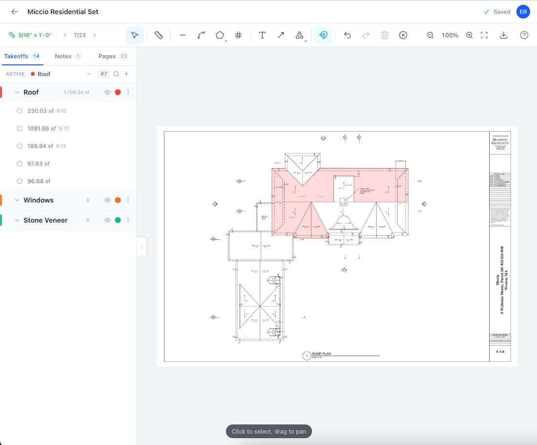
Start by uploading the full mechanical plan set as a PDF. Navigate to the supply air plan and set the drawing scale using a known dimension or the printed scale bar. Most mechanical plans are drawn at 1/4-inch equals 1 foot or 1/8-inch equals 1 foot. Begin with the supply air system: trace the main supply trunk from the air handler or RTU using the polyline tool, clicking at every branch takeoff, transition, and direction change. Then trace each branch duct to the register or diffuser. Create a "Supply Duct" measurement group for these traces. Switch to the return air plan and trace the return system in a separate group. Then do the same for exhaust ductwork. Use the count tool to mark every supply register, return grille, diffuser, fire damper, VAV box, and piece of equipment. Create separate count groups for each device type. Finally, trace refrigerant line sets between outdoor and indoor units if the project has split systems. Export everything to CSV and your quantities are organized by system and ready for the sheet metal fabrication order and bid pricing.
Waste factors vary by duct type. Sheet metal duct (galvanized spiral and rectangular) runs 8 to 12 percent waste. The waste comes from fabrication cutoffs at transitions, reducers, end caps, and field modifications. Rectangular duct wastes more than spiral because every fitting is custom-fabricated from flat sheet, generating irregular offcuts. Flex duct runs 3 to 7 percent because it bends without fittings, but the short runout lengths (typically 6 to 12 feet) from 25-foot boxes mean each box leaves a remnant. Duct board runs 10 to 15 percent because scoring and folding creates scrap at every corner, fitting, and transition. External duct insulation (fiberglass wrap) runs 8 to 12 percent due to the extra material consumed wrapping around elbows, tees, and fittings versus straight runs. Refrigerant line sets run 3 to 7 percent. Pre-charged sets come in fixed lengths, and the difference between the run measurement and the next available set length is waste. Apply waste factors per material type, not as a single blanket percentage across the project.
HVAC plan symbols for supply registers are typically rectangles with diagonal lines (indicating airflow direction), return grilles are rectangles with parallel lines, and diffusers are circles or squares with radial lines. Some engineers use custom symbols defined in the drawing legend. Check the legend before starting your count. In Easy Takeoffs, create a separate count group for each device type: supply ceiling registers, supply sidewall registers, return ceiling grilles, return wall grilles, linear slot diffusers, and any specialty items. Click on each symbol on the plan and the count updates in real time. After counting each floor, cross-reference your total against the mechanical schedule in the specifications. The schedule lists every terminal device by type, size, CFM rating, and quantity. If your plan count does not match the schedule, submit an RFI before bidding. Common miscount sources: registers hidden behind door swings on the plan, return grilles in hallway ceilings that blend into the architectural drawing, and transfer grilles in walls between rooms that are drawn differently than ceiling devices.
An HVAC takeoff measures the quantity of ductwork, equipment, and accessories from the mechanical drawings. A Manual D calculation is the engineering process that determines what duct sizes should be used based on airflow requirements, friction rate, and equivalent duct length. The takeoff tells you how much material to order. Manual D tells you what sizes to use. On most commercial projects, the mechanical engineer performs Manual D during design, and the duct sizes are noted on the drawings. Your takeoff simply measures the footage at the sizes shown. On residential new construction, the HVAC contractor often performs both Manual D (to size the duct system) and the takeoff (to quantify material for ordering). The Manual D calculation requires a Manual J load calculation first, which determines the CFM airflow needed for each room. Manual D then sizes the ducts to deliver that airflow within an acceptable friction rate (typically 0.08 to 0.10 inches of water column per 100 feet). The takeoff is downstream of Manual D. You cannot do an accurate takeoff until you know the duct sizes, either from the engineer drawings or your own Manual D.
Yes. Commercial mechanical plan sets are typically multi-page PDFs with separate sheets for each floor, each system (supply, return, exhaust, kitchen hood), equipment schedules, control diagrams, and duct riser details. Upload the entire set as a single PDF and navigate between pages within the project. Commercial HVAC takeoffs require more measurement groups than residential because the systems are more complex. A typical commercial takeoff might have 15 to 25 groups: floor 1 supply duct, floor 1 return duct, floor 1 exhaust, and so on for each floor, plus separate groups for kitchen hood ductwork, laboratory exhaust, stairwell pressurization, parking garage ventilation, and refrigerant piping. The count tool handles the higher device densities on commercial floors. A single commercial floor might have 40 to 80 terminal devices across supply, return, and exhaust systems, plus VAV boxes, fire dampers, and smoke dampers. Create separate count groups for each device type and export to CSV so your estimator can price duct material, equipment, and accessories as separate bid line items.
Refrigerant line sets connect outdoor condensing units to indoor evaporator coils on split systems, mini-splits, and VRF systems. Use the polyline tool to trace the routing path from the outdoor unit to each indoor unit. Start at the outdoor unit and follow the anticipated path: along the building exterior, through penetrations, across ceilings or in pipe chases, and to each indoor unit. The routing is rarely a straight line. Create separate measurement groups for each refrigerant circuit. A 4-zone mini-split has 4 separate line sets, each with a suction line and a liquid line. On VRF systems, also trace the branch piping from the Y-joints to each indoor head. The branch pipes are typically smaller diameter than the main header. Note the pipe diameter for each group because 3/8-inch liquid line costs differently than 7/8-inch suction line. Total footage determines refrigerant charge calculations and whether the system falls within the manufacturer maximum equivalent piping length. Pre-charged line sets come in fixed lengths (25, 35, 50 feet), so your measured footage determines which set to order and the waste from the length difference.
Digital HVAC takeoff from properly scaled PDFs is consistently more accurate than manual scaling on paper. Manual takeoffs introduce error from ruler placement, scale reading, and transcription. A 1/16-inch misread at 1/4-inch scale equals 3 inches in the real world. Over 30 duct runs, those errors compound to 5 to 10 percent variance from actual installed footage. Digital tracing eliminates parallax and reading errors because the software calculates footage directly from the calibrated scale. Digital takeoffs typically land within 2 to 3 percent of installed measurements. The bigger accuracy gain is completeness. Manual takeoffs miss duct runs because the estimator skips a section of a dense drawing, loses track of which branches have been measured, or forgets an entire page of the plan set. Digital markers on the plan make omissions visible because unmarked duct runs stand out against the measured ones. Accuracy also depends on drawing quality. If the engineer drew duct routing to scale, the digital trace is accurate. If the routing is schematic (showing connections but not actual paths), add routing allowances for the real-world path.
A complete HVAC takeoff requires the mechanical plan sheets (M-series drawings), which show duct routing, terminal device locations, equipment placement, and pipe routing on each floor. These are your primary measurement sheets. You also need the mechanical schedules, usually on the first or last mechanical sheet, which list every piece of equipment and every terminal device with tag numbers, manufacturers, models, capacities, and quantities. Beyond the M-series, the architectural floor plans provide room dimensions and ceiling heights needed for duct drop calculations and duct board plenum sizing. Structural plans show beam locations, bar joist directions, and slab penetrations that affect duct routing. The project specifications (Division 23) define materials, insulation requirements, testing procedures, and acceptable manufacturers. For commercial projects, you may also need the controls drawings for thermostat counts and control valve quantities, and the fire protection drawings for coordination around sprinkler mains. Upload all relevant pages into the same Easy Takeoffs project and switch between them while building your takeoff. Having the architectural plans alongside the mechanical plans lets you verify ceiling heights and coordinate routing clearances.
Duct size changes at every transition, reducer, and branch takeoff along the system. The mechanical drawings note the size at each change point. You have two approaches for tracking sizes. The first is to create a separate measurement group for each duct size: "12-inch round supply," "10x8 rectangular supply," "6-inch round supply runout." This gives exact footage per size for fabrication ordering but creates many groups on a large project. The second approach is to trace each system as a continuous run in one group and note duct sizes in the group name or description. The CSV export gives total footage per group, and you annotate sizes manually on the fabrication order. Most experienced estimators use the first approach for the main trunk sizes and the second for smaller branches, since the shop needs exact trunk footage by size but can work with approximate branch totals. For flex duct runouts, a single group usually works because most runouts on a residential system are the same diameter (6-inch or 8-inch). On commercial systems where runout sizes vary by zone, separate groups by size.
A residential HVAC takeoff for a 2,500 square foot single-family home with a single-zone system takes 20 to 40 minutes with digital takeoff software. The supply trunk, branches, and 10 to 15 runouts trace quickly. Add 15 minutes for the return system and equipment counts. The same job takes 2 to 3 hours manually on paper. A commercial tenant buildout of 10,000 square feet with supply, return, and exhaust systems takes 2 to 4 hours digitally and 6 to 10 hours manually. A 5-story commercial building with multiple air handlers, VAV systems, kitchen hood exhaust, and stairwell pressurization can take 6 to 10 hours digitally. The time savings with digital takeoff compound on larger projects because measurement groups carry over between floors. If floors 2 through 5 have identical layouts, you take off one floor completely and note the multiplier. Manual takeoffs require tracing each floor individually. Multi-building projects like apartment complexes show the biggest digital advantage because repeating units only need to be taken off once.
Organize your HVAC takeoff by system first, then by floor. Create measurement groups in this order: supply ductwork (trunk and branches), supply runouts (flex or round), return ductwork, exhaust ductwork, kitchen hood ductwork (if applicable), and refrigerant piping. Within each system, subgroup by floor for multi-story projects. For equipment and device counts, create groups by type: supply registers, return grilles, diffusers, VAV boxes, fire dampers, smoke dampers, volume dampers, access doors, RTUs, AHUs, condensing units, and exhaust fans. This organization matches how HVAC bids are structured. The duct fabrication scope, the equipment scope, the insulation scope, and the controls scope are typically separate line items or even separate subcontracts. Your takeoff groups should map directly to these bid divisions. Export to CSV and each group becomes a line on the bid sheet without manual reformatting. For very large projects, add a prefix to each group name with the building or wing designation so the CSV sorts cleanly.
Yes, and fittings are where many HVAC takeoffs fall short. Duct fittings include elbows (90-degree and 45-degree), tees, wyes, reducers, transitions (rectangular to round), end caps, offsets, and takeoff collars. On a commercial system, fittings can represent 20 to 30 percent of the total sheet metal fabrication cost. The sheet metal shop needs to know fitting quantities by type and size to price the fabrication accurately. When you trace a duct run with the polyline tool, each click point at a direction change represents a potential fitting. Count the direction changes in each trace to approximate elbow and tee quantities. For more precise fitting counts, create separate count groups for each fitting type and mark them individually on the plan. Most mechanical drawings show fittings symbolically. Elbows appear as curved sections, tees as T-junctions, and transitions as tapered sections. The waste factor for sheet metal duct already accounts for the extra material consumed in fabricating fittings, but the labor hours for installing fittings are significantly higher than for straight duct. Your estimator needs both the duct footage and the fitting count to price labor accurately.
Yes. Easy Takeoffs includes the HVAC Rectangular Duct template. Apply it to a measurement group and it calculates sheet metal weight, insulation wrap area, duct hangers, and fitting quantities from your measured linear footage. You set the duct width and height to match the mechanical plans, choose the insulation type (none, fiberglass wrap, or duct liner), and adjust the fitting factor to account for the complexity of the duct routing. The template includes waste factors and rounds to practical order quantities so the numbers are ready for the sheet metal fabrication shop.
Start Your Construction Takeoff Today
Upload your first PDF plan set, set the scale, and pull accurate quantities before lunch. $39 a month after the trial, less than every dedicated competitor.