Do a framing takeoff by reading each wall run, opening, corner, and detail into a member schedule before adding anything to a lumber list. Then reconcile that schedule to cut pieces, stock lengths, and a stated waste allowance. The worked exercise below shows the method on two small wall panels. Its drawings and member schedule are estimating inputs, not a structural design or installation instruction.
For a PDF set, takeoff software keeps the wall runs and opening locations tied to the drawing and carries the quantity record into an annotated PDF and CSV. Easy Takeoffs measures plans, organizes the quantities, and exports the record for $39 a month or $399 a year after a 14-day trial. It does not price labor or materials for you.
What a framing takeoff is trying to prove
A framing takeoff is a traceable answer to a simple question: which pieces belong to this scope, and where did each one come from? A total stud count alone cannot answer it. A reviewer needs to see the wall run, the opening that displaced a field position, the short members that appear above or below that opening, and the assumptions used to buy stock.
Start by separating the information on the plans into two lists:
- Geometry: wall IDs, measured lengths, wall height, opening locations and rough-opening dimensions.
- Specified framing: the stated wall type, spacing, plates, opening details, intersections, notes, and any engineered or structural callouts.
The plan view may give the first list, but elevations, sections, wall types, schedules, and structural sheets can change the second. That is why a dependable lumber list starts from the drawings and details, not from a shortcut such as wall length divided by spacing plus a fixed number for every opening. The 2024 IRC wall-framing provisions distinguish among wall and opening conditions, and the American Wood Council's 2024 Wood Frame Construction Manual likewise treats wall systems as design work with stated limits and loads.
Those sources are context, not the design basis for this exercise. On an actual bid, use the issued drawings, specifications, addenda, and any required clarification. Do not infer a header, king stud, jack stud, spacing, or bracing detail that the documents have not established.
Put positions before piece counts
Lay out a wall from a named reference point. Mark the ends, corners or intersections, opening edges, and any positions already occupied by the schedule. Then place only the remaining field positions that the wall type calls for. This makes ownership visible: a full-height member cannot be counted once as a field stud and again as an opening member merely because it is near an opening.
Treat each opening as its own assembly in the schedule. The scheduled parts may include full-height members, supporting members, a header, a sill, and short members. Their sizes and counts belong to the exercise detail or project documents. They are not universal quantities that a takeoff should manufacture from the opening width.
If you need to establish a PDF scale before pulling the wall runs, the practical steps are in how to measure a PDF. The same habit of tracing a quantity back to its source also matters in a drywall takeoff from blueprints, even though the material rules are different.
Worked example: two wall panels and a changed opening
Worked plan: original opening
Synthetic nonbearing practice detail. The listed sizes and cuts are exercise givens, not construction guidance. Header packers are excluded from this lumber-only schedule.
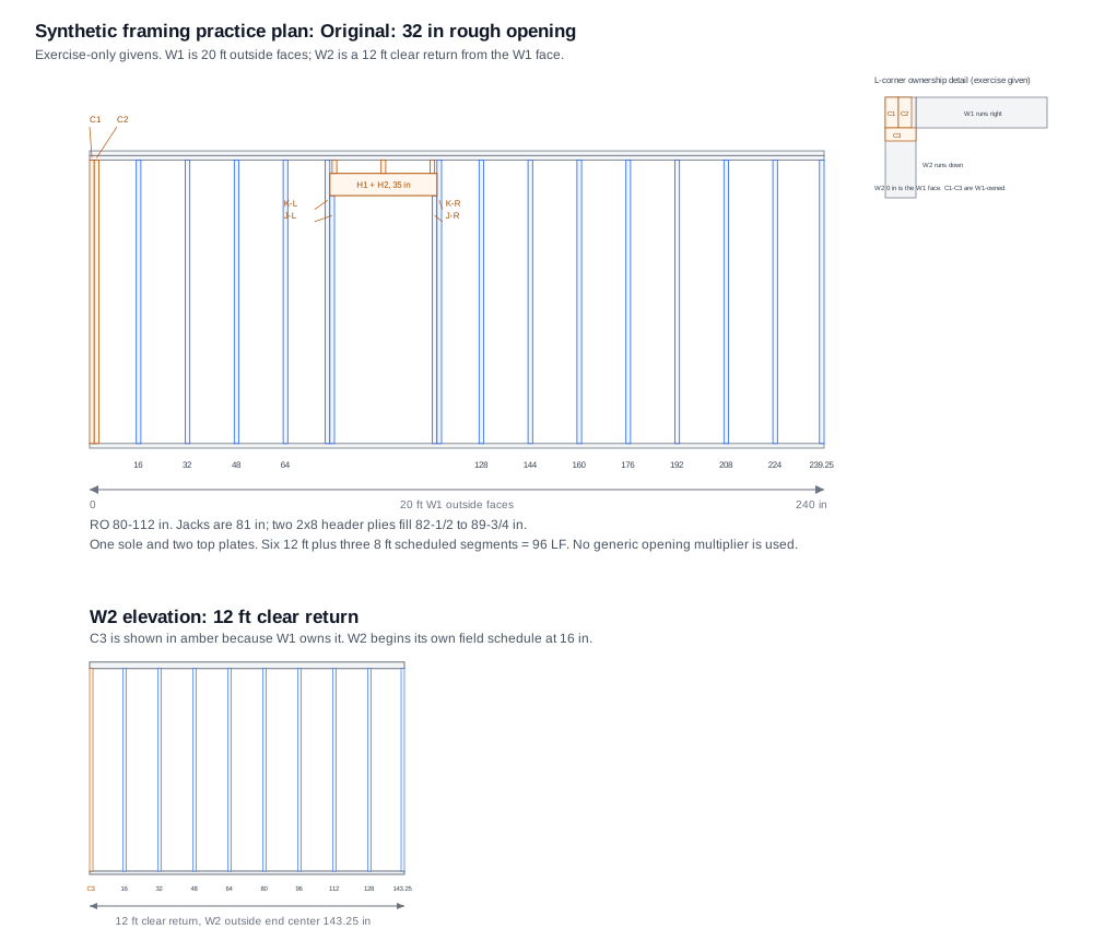
W1 is 20 ft outside faces. W2 is a 12 ft clear return from the W1 face. C1 through C3 belong to W1, so W2 has no duplicate corner end stud.
Open full-size drawing (opens in a new tab)Checked member schedule
Field centers are inches from each panel's left reference. Actual opening faces and member centers are listed separately.
| Members | Exact assignment | Count |
|---|---|---|
| L corner | C1, C2, C3, W1-owned full-height 2x4 x 92-5/8 | 3 |
| W1 field | 16, 32, 48, 64, 128, 144, 160, 176, 192, 208, 224, 239.25 | 12 |
| W2 field | 16, 32, 48, 64, 80, 96, 112, 128, 143.25 | 9 |
| Opening full-height | K-L at 77.75 in; K-R at 114.25 in | 2 kings |
| Opening short pieces | J-L at 79.25 in and J-R at 112.75 in, 81 in each; 3 cripples, 4-3/8 in each | 2 jacks + 3 cripples |
| Given header | Two 2x8 plies from 78.5 in to 113.5 in | 2 x 35 in |
| Plate layers | One sole plus two top layers. Each has W1 12 + 8 ft and W2 12 ft segments. | 96 LF |
Worksheet and purchase convention
The 10% allowance is applied to net material first. Stock rows show the independent board-length rounding, not an optimized order.
| Item | Net schedule | After 10% | Stock result |
|---|---|---|---|
| 2x4 x 92-5/8 stock | 26 full-height + 2 jack source pieces = 28 | 30.8 | 31 pieces |
| 2x4 plate length (reference) | 6 x 12 ft + 3 x 8 ft = 96 LF | 105.60 LF | 9 x 12 ft = 108 LF |
| 2x8 header length (reference) | 2 x 35 in = 70 in raw | 70 in x 1.10 / 12 = 6.42 LF | 1 x 8 ft |
Rough opening: 32 in wide, from 80 in to 112 in. Header bottom is 82-1/2 in from the floor; its 7-1/4 in depth and 4-3/8 in cripples fill the elevation to the double top plates.
This synthetic, nonbearing exercise gives W1 a 20-foot outside-face length and W2 a 12-foot clear return. The source drawing assigns the three-member L corner to W1. C3 appears in W2's elevation for orientation, but remains W1-owned, so W2 does not gain a duplicate end stud at that corner.
On the original drawing, W1 has 12 scheduled field positions and W2 has nine. Add the three W1-owned corner members and the two full-height opening members, and the full-height total is 26. The opening also has two 81-inch jacks, three 4-3/8-inch cripples, and two given 2x8 header plies at 35 inches. Three plate layers use six 12-foot segments and three 8-foot segments for 96 linear feet. A header packer is outside this exercise's scope, along with sheathing, fasteners, blocking, insulation, and any member not listed in the schedule.
The point is not that another wall should use these pieces. The exercise makes each of them visible and owned. A reviewer can add the schedule independently: 12 W1 field members, nine W2 field members, three corner members, and two opening kings. The jacks, cripples, header plies, and plate segments stay on their own lines rather than disappearing into a generic “opening” adjustment.
Download the original practice drawing and its fixed worksheet if you want to check the positions and arithmetic away from the article.
Count locations and scheduled members, then total the schedule. Do not start with a total and try to explain the missing pieces afterward.
Reconcile the schedule into a lumber list
The schedule is the net quantity. The order list is a separate decision. Keeping those two stages separate prevents waste, short pieces, and stock rounding from hiding inside a single number.
Keep full-height and cut pieces distinct
First group the scheduled pieces by material and cut length. A full-height member, a header component, a plate segment, a sill, and a short member should remain separate lines until their uses have been checked. The cut-piece list should still identify its wall or opening, even if the purchase list later combines matching stock.
This is also where the drawing exposes an easy mistake: a window may create short members that do not appear in a door panel, while a changed rough opening can change the header and its supporting pieces without changing the overall wall length. The schedule, not a generic per-opening allowance, carries that difference.
Convert cut pieces to buy lengths deliberately
Next, choose stock lengths that can produce the scheduled cuts with practical offcuts. A supplier may offer several lengths, and a takeoff should show which buy length was chosen rather than quietly treating all lumber as interchangeable linear feet. Keep a piece needed at its full length separate from leftovers that happen to be long enough on paper but do not fit the planned cut sequence.
For the original exercise, the 26 full-height members plus two precuts used as jack source pieces make 28 precuts before waste. The stated 10% allowance rounds that row to 31 pieces. The 96 linear feet of plates becomes 105.60 linear feet after the same allowance, then rounds to nine 12-foot boards, or 108 linear feet. The two 35-inch header plies total 5.83 linear feet, become 6.42 linear feet after the allowance, and fit the exercise's one 8-foot header board.
Each 81-inch jack leaves an 11-5/8-inch gross offcut from its 92-5/8-inch precut, or 11-1/2 inches usable after the jack cut's 1/8-inch kerf. With a 1/8-inch kerf for each cripple cut, the two offcuts support the shown three original cripples and four revised cripples. Those cripple cuts use stock already counted for the jacks. Do not add them again as separate short stock or apply a second waste allowance to the completed purchase count. That is a cut check, not a claim that every lumberyard order should follow this exact sequence.
Apply the stated waste allowance after the net schedule and stock plan are visible. Waste covers the uncertainty and cutting loss allowed by the estimating assumption. It does not correct a missing corner, an unrecorded opening member, or a drawing conflict. Round the resulting purchase quantities to whole stock pieces and retain the net quantity, allowance, and final order quantity as separate values.
Export the evidence with the quantity
An estimator should be able to hand off two records: the quantity file for pricing and the marked drawing that explains it. In the practice exercise, the CSV keeps the scheduled groups and totals visible, while the annotated PDF shows the wall-panel measurements on the source drawing. We created the practice drawings and checked the fixed member schedule for this guide. The CSVs and three-page annotated PDFs use Easy Takeoffs' actual export functions with those practice measurements and material quantities. These are practice files, not customer projects.
That distinction matters when the list reaches a supplier or another estimator. The CSV makes it easier to price or re-sort the material. The annotated PDF answers the next question, which is usually, “Where did this run come from?” Easy Takeoffs can export both a spreadsheet-ready CSV and an annotated PDF from the stored measurements. The software preserves the takeoff record. It does not replace a supplier quote, structural review, or the estimator's pricing judgment.
Turn a measured plan into a reviewable quantity record
Use a completed job to test the workflow that matters: measure the scope, check every total against the drawing, and open both exports before you price it. The 14-day trial includes the full software.
Review the revised opening as a change to the schedule
The revised practice drawing widens the rough opening from 32 inches to 48 inches while W1 remains 20 feet long. Do not update only the opening width and leave the original takeoff standing. Review the wall panel, opening reference, scheduled members, any short pieces, the header line, and the stock plan that depended on them. Then compare the original and revised net lists before changing the purchase quantity.
Revision check: widened opening
Synthetic nonbearing practice detail. The listed sizes and cuts are exercise givens, not construction guidance. Header packers are excluded from this lumber-only schedule.
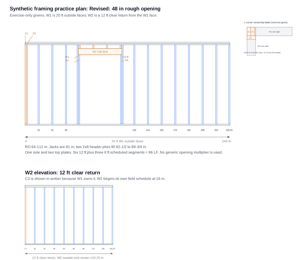
W1 is 20 ft outside faces. W2 is a 12 ft clear return from the W1 face. C1 through C3 belong to W1, so W2 has no duplicate corner end stud.
Open full-size drawing (opens in a new tab)Checked member schedule
Field centers are inches from each panel's left reference. Actual opening faces and member centers are listed separately.
| Members | Exact assignment | Count |
|---|---|---|
| L corner | C1, C2, C3, W1-owned full-height 2x4 x 92-5/8 | 3 |
| W1 field | 16, 32, 48, 128, 144, 160, 176, 192, 208, 224, 239.25 | 11 |
| W2 field | 16, 32, 48, 64, 80, 96, 112, 128, 143.25 | 9 |
| Opening full-height | K-L at 61.75 in; K-R at 114.25 in | 2 kings |
| Opening short pieces | J-L at 63.25 in and J-R at 112.75 in, 81 in each; 4 cripples, 4-3/8 in each | 2 jacks + 4 cripples |
| Given header | Two 2x8 plies from 62.5 in to 113.5 in | 2 x 51 in |
| Plate layers | One sole plus two top layers. Each has W1 12 + 8 ft and W2 12 ft segments. | 96 LF |
Worksheet and purchase convention
The 10% allowance is applied to net material first. Stock rows show the independent board-length rounding, not an optimized order.
| Item | Net schedule | After 10% | Stock result |
|---|---|---|---|
| 2x4 x 92-5/8 stock | 25 full-height + 2 jack source pieces = 27 | 29.7 | 30 pieces |
| 2x4 plate length (reference) | 6 x 12 ft + 3 x 8 ft = 96 LF | 105.60 LF | 9 x 12 ft = 108 LF |
| 2x8 header length (reference) | 2 x 51 in = 102 in raw | 102 in x 1.10 / 12 = 9.35 LF | 2 x 8 ft |
Rough opening: 48 in wide, from 64 in to 112 in. Header bottom is 82-1/2 in from the floor; its 7-1/4 in depth and 4-3/8 in cripples fill the elevation to the double top plates.
The widened opening removes W1's 64-inch field position and moves the left king to 61-3/4 inches. It adds one cripple and changes the given header from 35 to 51 inches. The full-height count falls from 26 to 25, while the cripple count rises from three to four. The net precut stock changes from 28 to 27 and, with the same stated allowance applied once, the purchase count changes from 31 to 30 pieces. The plate order stays at nine 12-foot boards, and the header order changes from one to two 8-foot boards. A stable wall length did not produce a stable lumber list.
In Easy Takeoffs, a revision comparison flags measurements on changed pages for review. That focuses attention on work that may need rechecking, but it does not automatically correct the quantity or guarantee that every change has been caught. The estimator still compares the drawing, confirms the applicable schedule, and updates the affected material lines.
When an opening changes, review the schedule and its purchase plan together. A wall length that stays the same can still have a different lumber list.
Frequently Asked Questions
How do you count studs from blueprints?
Read the wall type and drawing details first, then lay out the wall from a fixed reference point. Record end conditions, corners, intersections, openings, and the positions they occupy before filling the remaining scheduled field locations. Keep opening members, headers, sills, and short pieces as separate lines until the wall schedule is complete. This produces a list another person can trace back to the drawing. A length-and-spacing calculation can be a useful check for a simple run, but it cannot decide which project-specific members belong at corners or openings.
What drawings do you need for a framing takeoff?
Use the floor plan for wall locations, dimensions, and opening references, then check the wall types, elevations, sections, details, schedules, structural sheets, specifications, and addenda that govern the members. A plan view alone can leave out the information that changes a lumber list, such as an opening detail, a changed wall type, a structural note, or a condition at an intersection. If the documents conflict or omit a needed item, label the assumption or request clarification. A precise measured length does not resolve an unspecified framing detail.
What should you review when a window or door changes?
Start with the revised sheet and confirm that the page mapping is correct. Recheck the wall run, opening location, rough-opening dimensions, the applicable detail, and every scheduled member tied to that opening. Then compare the former and revised net lists, including short pieces and headers, before revising waste or stock rounding. Check the annotated drawing and the CSV after the change so the visible evidence agrees with the pricing quantity. Do not assume an unchanged wall length means the lumber order remains unchanged.
Can a framing calculator do a plan takeoff?
A framing calculator is useful when you already know the wall length, height, spacing, and opening inputs. It can quickly show rough wall quantities and make its math visible. It does not read the plan, determine which detail applies, place members around an opening, or preserve a drawing-backed audit trail. Use the framing calculator to check a typed wall scenario. Use a drawing-based takeoff and the project documents when the quantity must trace to a bid set.